Induction Motor Wiring Diagrams
Wiring induction wire shaft output viewed when Induction motor working principle diagram Induction phase alpak pole motors
Induction Motor Working Principle Diagram
Support and application data/wiring diagrams for our products Show & tell: ac induction motors Induction wiring motors
Induction phase capacitor circuit speed 230v csim electricalacademia
Phase induction pole capacitor shaded electrical4u flux disadvantagesCircuit phase motor induction equivalent single diagram rotor two split now speed winding Wiring diagram of direct on line starting three phase induction motorMotor phase diagram wiring single induction electric split motors capacitor types run connection leads explained schematic fig electrical internal gif.
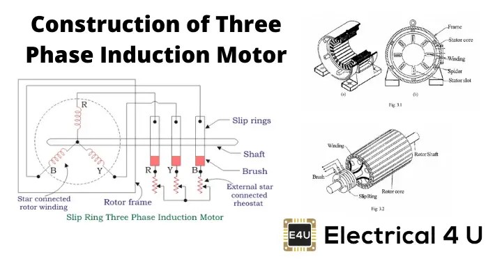
Induction operation phase coupling engineeringlearnMotor induction phase slip three ring diagram resistance types external working electrical applications shown below figure construction Clarke single phase induction motor wiring diagramTypes of single phase induction motors (split phase, capacitor start.
![What is 3 Phase Induction Motor? Diagram, Working & Types](https://i2.wp.com/electricalworkbook.com/wp-content/uploads/2021/06/Three-Phase-Induction-Motor-1-768x374.png)
Phase motor single induction diagram wiring electric ac clarke start does 220v capacitor electrical circuit winding torque doerr motors supply
Three phase induction motor: types, working, and applicationsWhat is 3 phase induction motor? diagram, working & types Equivalent circuit of a single phase induction motorCapacitor-start induction motor (csim) circuit (wiring) diagram and.
Alpak induction motor wiring diagramInduction electricalworkbook rotor Induction wiringOperation of induction motor.
![Equivalent Circuit of an Induction Motor - Rotor & Stator Circuit](https://i2.wp.com/circuitglobe.com/wp-content/uploads/2016/02/EQUIVALENT-CIRCUIT-OF-AN-INDUCTION-MOTOR-FIG-1.jpg)
Equivalent circuit of an induction motor
Induction principleTypes of single phase induction motors Circuit induction equivalent motor stator fig diagram phase resistance current magnetizing load winding model transformer reactor electrical rotor.
.
![Clarke Single Phase Induction Motor Wiring Diagram](https://i2.wp.com/schematron.org/image/clarke-single-phase-induction-motor-wiring-diagram-2.jpg)
![alpak induction motor wiring diagram - Wiring Diagram](https://i2.wp.com/www.ato.com/Content/Images/uploaded/3-phase-induction-motor-wiring-connection-diagram.jpg)
![Capacitor-start induction motor (CSIM) circuit (wiring) diagram and](https://i2.wp.com/electricalacademia.com/wp-content/uploads/2018/04/Capacitor-start-induction-motor-CSIM-circuit-wiring-diagram-and-torque-speed-curve.-1024x535.jpg)
![Induction Motor Working Principle Diagram](https://i2.wp.com/www.yourelectricalguide.com/wp-content/uploads/2018/11/three-phase-induction-motor-working-principle-1.jpg)
![Types of Single Phase Induction Motors | Single Phase Induction Motor](https://i2.wp.com/electricala2z.com/wp-content/uploads/2017/11/Fig.6-Split-Phase-Motor-Wiring-Diagram.gif)
![Support and Application Data/Wiring Diagrams for our products](https://i2.wp.com/www.motiondynamics.com.au/motorimages/wiring_induction_motor.jpg)
![Operation of Induction Motor - Engineering Learner](https://i2.wp.com/engineeringlearn.com/wp-content/uploads/2021/03/Operation-of-Induction-Motor-Three-Phase-Induction-Motor-1024x539.jpg)
![Types of Single Phase Induction Motors (Split Phase, Capacitor Start](https://i2.wp.com/www.electrical4u.com/wp-content/uploads/What-are-the-Types-of-Single-Phase-Induction-Motor.png)
![Equivalent Circuit of a Single Phase Induction Motor - Circuit Globe](https://i2.wp.com/circuitglobe.com/wp-content/uploads/2016/02/EQUIVALENT-CIRCUIT-OF-A-SINGLE-PHASE-INDUCTION-MOTOR-FIG-2.jpg)
![Wiring Diagram Of Direct On Line Starting Three Phase Induction Motor](https://i2.wp.com/www.electrical4u.com/wp-content/uploads/Construction-of-Three-Phase-Induction-Motor.png)